Admin UI
The Map
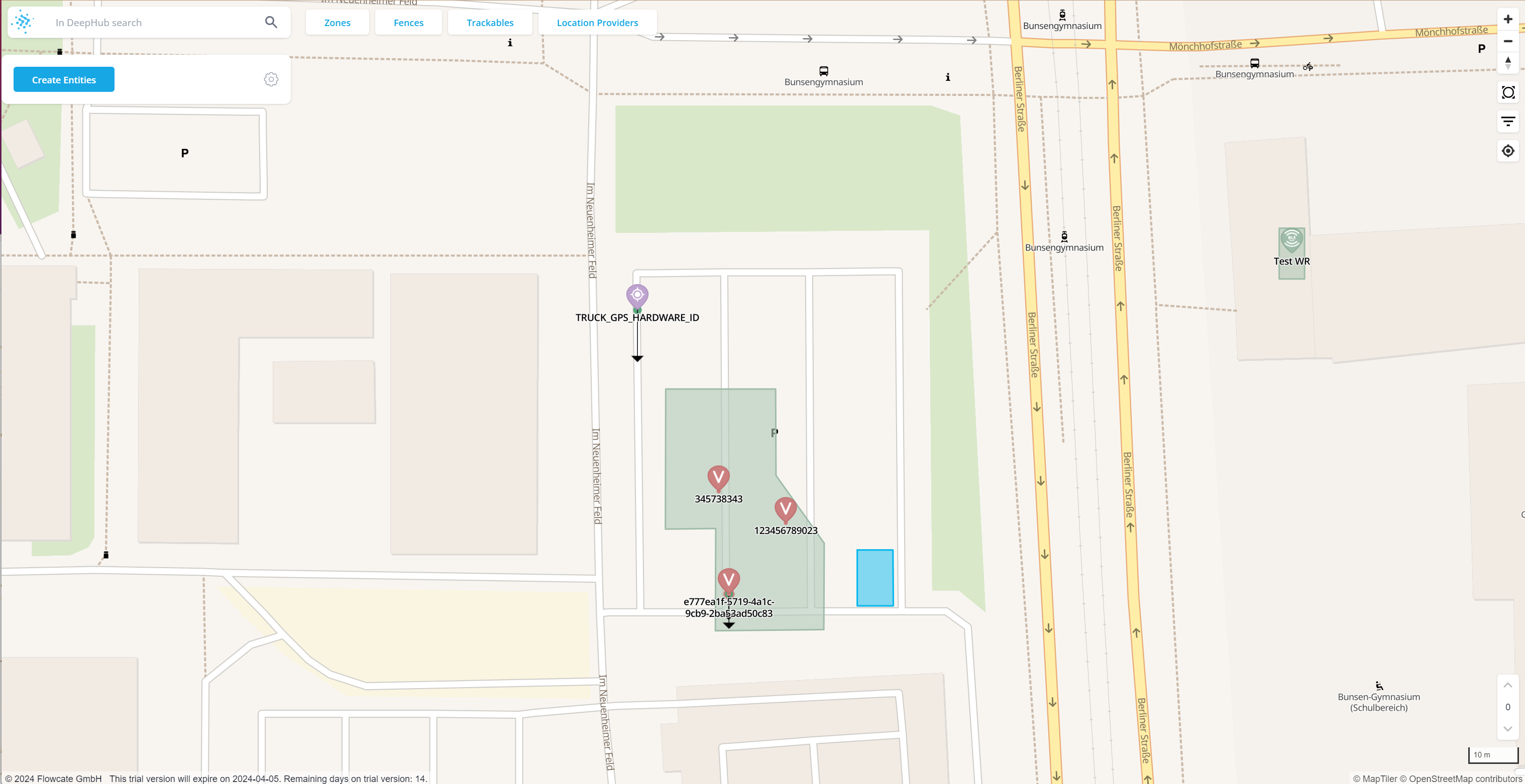
The map covers the whole view; there is intentionally no border, header, or footer. At the top, four quick filters are available: "Zones", "Fences", "Trackables" and "Location Providers". By clicking one of these filters, all entities of the corresponding type will be listed.
Below the search field on the top left, the main navigation menu of the Admin UI is visible: it allows for the creation of entities through the blue "Create Entities" button, and includes the "Global Settings" menu, visualized with the gear symbol.
At the top right corner, there are overlays/widgets to increase/decrease the zoom level of the map, reset the bearing to North, locate your current device, etc. These widgets can be thought of as the "viewing settings" of the Admin UI.
Finally, the floor level switcher is located at the bottom right corner of the UI.
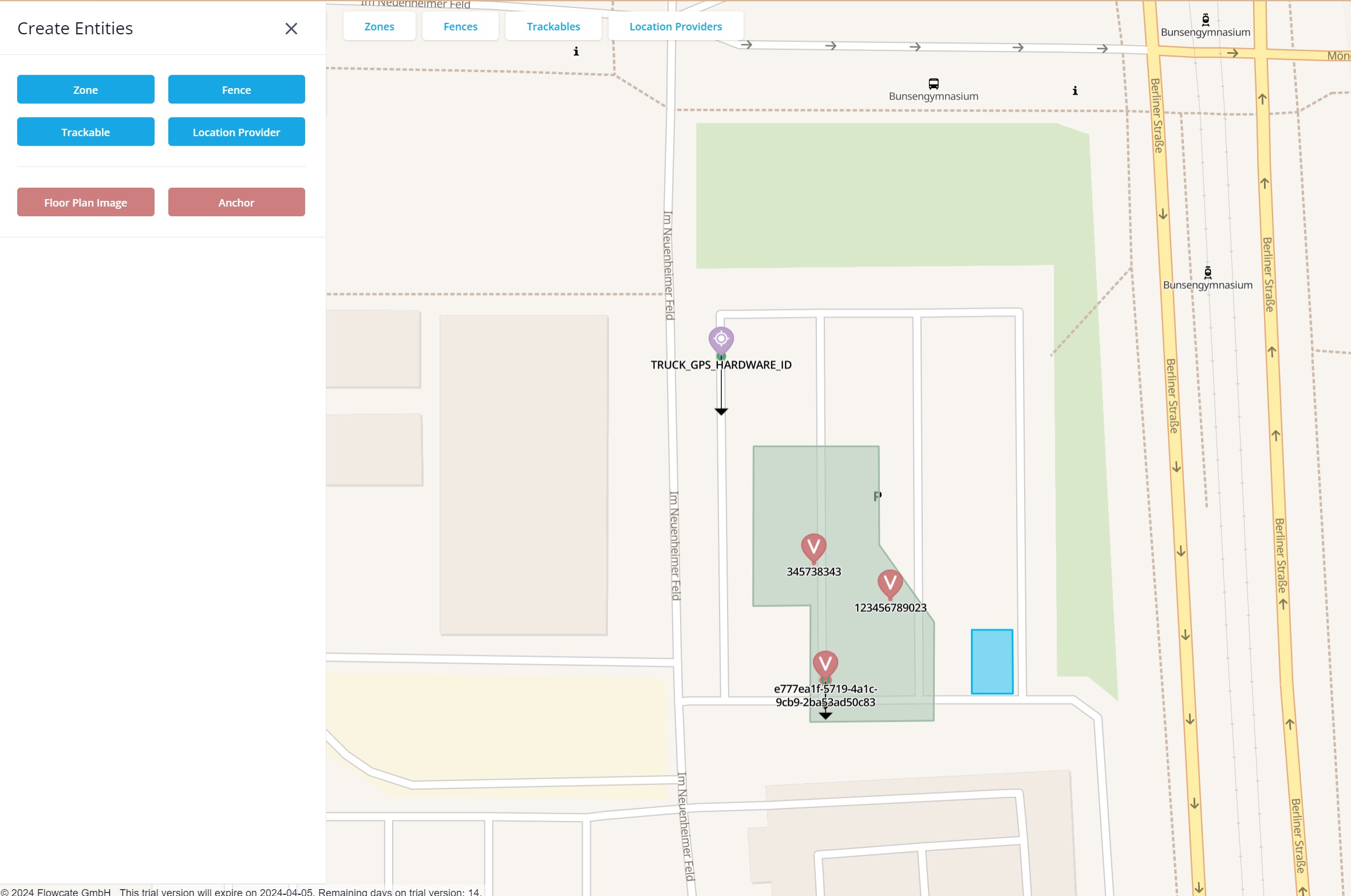
The "Create Entities" menu allows for the creation of omlox entities: "Zones", "Fences", "Trackables" and "Location Providers". It also allows for the creation of additional entities, including "Floor Plan Images" and "Anchors".
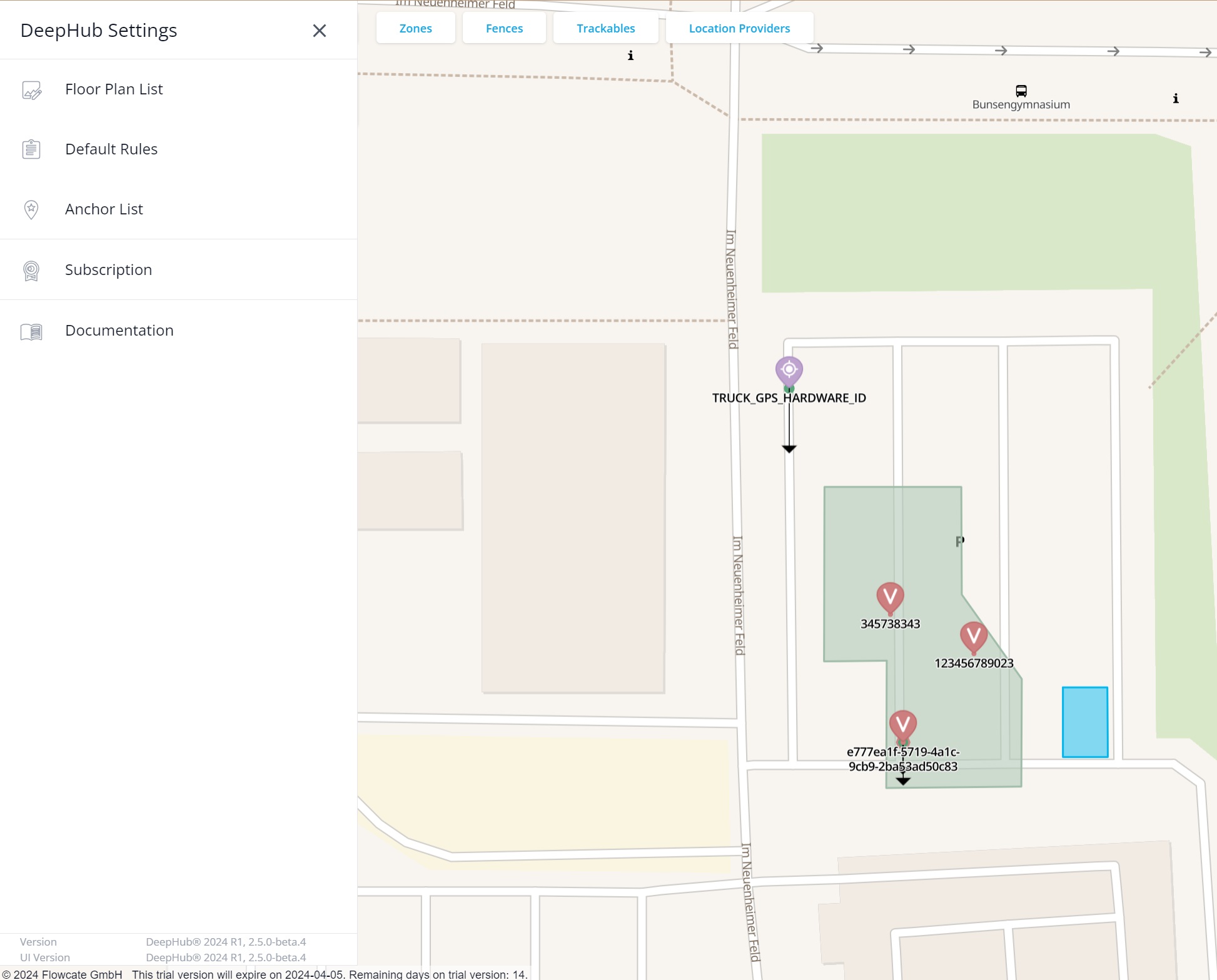
In the Settings menu, several options and settings can be adjusted or viewed. The active license key can be changed, and there is a link to the DeepHub documentation. Furthermore, the version of the DeepHub and the DeepHub UI is shown at the bottom.
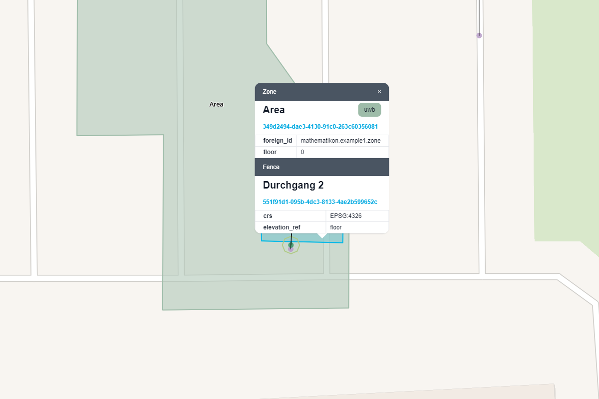
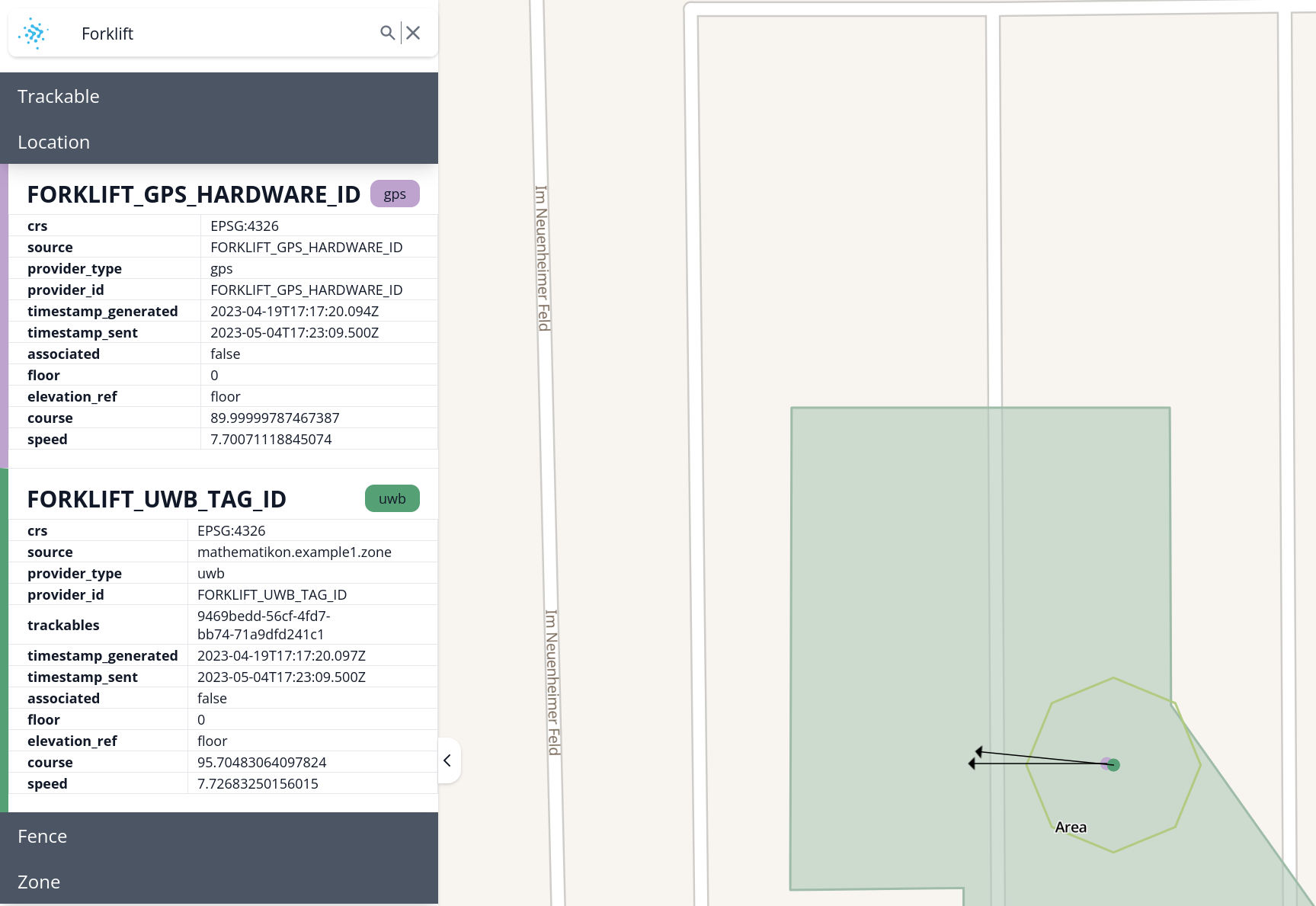
By left clicking on a fence (blue area), a zone (green area), a trackable, or a location provider within the map, a popup opens with information for all entities corresponding with the location that was clicked. In the example shown below, a zone and a fence were clicked at the same time:
Search Capabilities
The search field is at the top left corner of the UI. The blue DeepHub logo will change to red if the connection to the DeepHub was lost, or yellow if the connection is being re-established.
You can search for any known entity within the search field by using its id, name, or custom properties. The search happens immediately and incrementally. Whenever you start typing, the search begins based on the entered characters. When the search matches entities, the entities will be shown as a list below the search field. By clicking on a result, the map will pan and zoom directly to the corresponding entity.
If the results are insufficient, you can click on the magnifying glass symbol or press enter on your keyboard to get a detailed list of all search results right beneath the search field.
Look-and-Feel Settings
The look-and-feel of the Admin UI can be configured through the "viewing options" dialog window. To open this window, navigate to the top right corner of the UI and click this button:

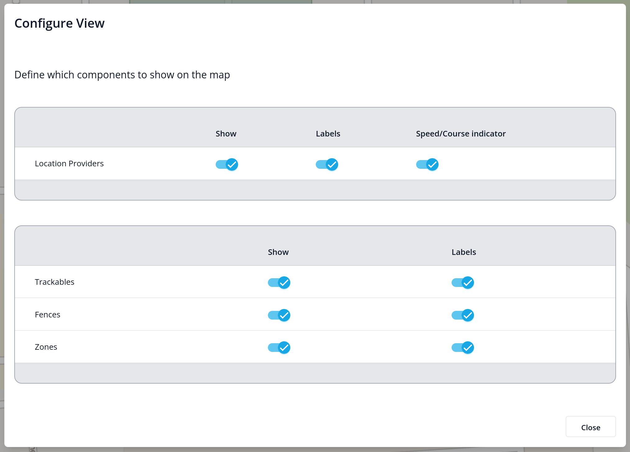
Within the "viewing options" dialog, you can enable or disable the rendering of location providers, trackables, fences, and zones. If rendering is enabled, you can switch certain rendering details on or off:
Floor Plan Images
The DeepHub can display floor plans on top of the map so that the interior of halls and buildings can be visualized. Floor plans can be uploaded in the form of an image file. All standard image formats are supported, such as jpeg, tiff, png, etc.
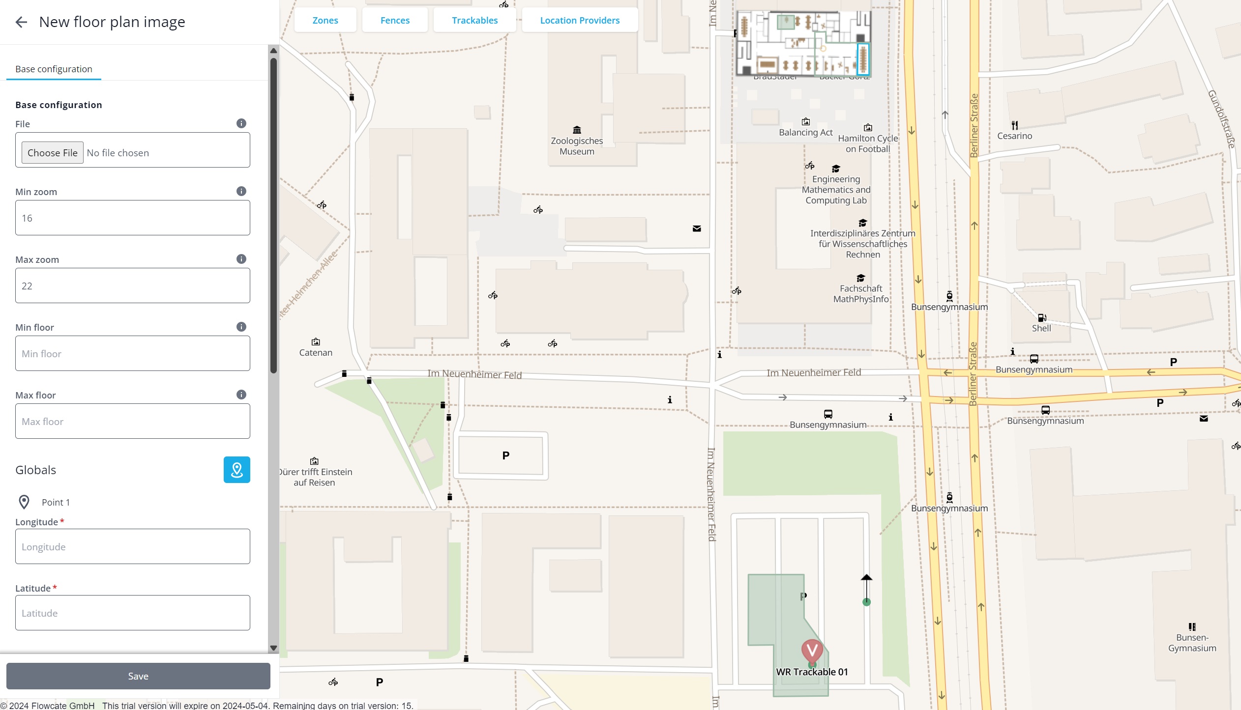
To upload a floor plan, click "Create Entities" and then "Floor Plan Images". In the floor plan widget, first select the file to upload. To maximize performance, an uploaded image is not simply stored and rendered but is actually handled by a "tile server". It is therefore optimized to be displayed at different zoom levels.
The next two settings, "Min zoom" and "Max zoom", specify the zoom levels of the map at which the floor plan image should be rendered and made available by the tile server in the background.
The "Min floor" and "Max floor" settings determine the floor levels upon which the floor plan image is rendered. These can be left empty if the floor plan image should be rendered on all floor levels.
The "Globals" settings specify where the floor plan image is drawn on the map. You can either enter the longitude and latitude associated with each corner of the floor plan image, or you can click on the blue "location" button next to the "Globals" heading to activate the "draw on map" mode. In this mode, simply click on the map to create the four corner points. The points must be drawn clockwise. To "close" the rectangle and complete the drawing, click again on the first corner point.
Hit "Save", and the image will be uploaded to the tile server to be processed. Depending on the size of the image and the chosen "Min zoom" and "Max zoom" settings, this may take several seconds to complete.
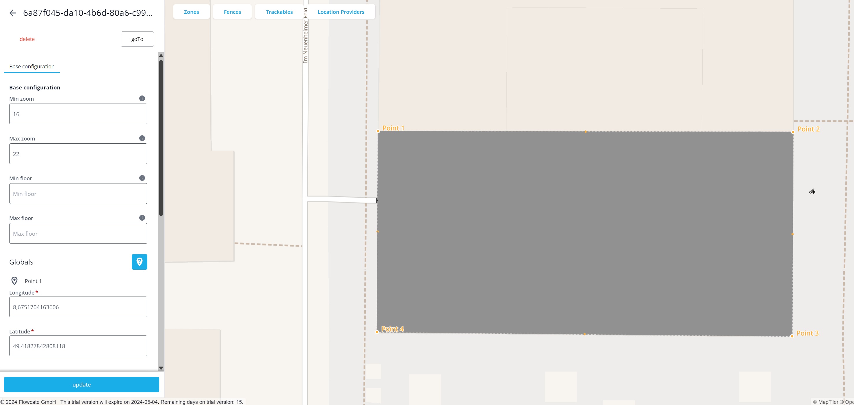
You can edit an existing floor plan image by going to the "Global Settings" menu and choosing "Floor Plan List". This option lists all uploaded floor plan images. By clicking on the floor plan you want to edit, the same widget from the initial uploading stage will pop up. From here, alter the settings you want to change and hit the "Update" button at the bottom.
Locating System Abstraction Level
The base entities of the DeepHub can be divided into two categories: the entities that represent the low-level abstraction of a locating system, and the entities that are used for business logic and application development. This chapter focuses on the former, specifically: zones, anchors and location providers.
The infrastructure of a real-time locating system consists of receivers placed on walls or ceilings, spanning an area within which tags can be located. These receivers are often called "anchors", "satellites" or "locators". They are represented in the DeepHub as "Anchor" entities. It is not mandatory to configure them within the DeepHub, however they help in providing a comprehensive overview of the system without having to switch to the software of the locating system vendor.
The area covered by these receivers, within which tags are tracked, is represented as a "Zone". A zone may be an "RTLS zone", providing x,y,z coordinates, or a "Proximity Zone", which detects if a tag is nearby. Whether a zone is an RTLS zone or a proximity zone is directly related to the chosen technology and does not need to be set separately.
A tag is represented as a "Location Provider" in the DeepHub.
One zone needs to be defined for each locating system connected to a DeepHub.
Creation and Management of Zones
To create a zone, choose "Create Entities" and then "Zone". This will bring you to the "New Zone" widget that shows a pre-generated Id for the new zone to be created:
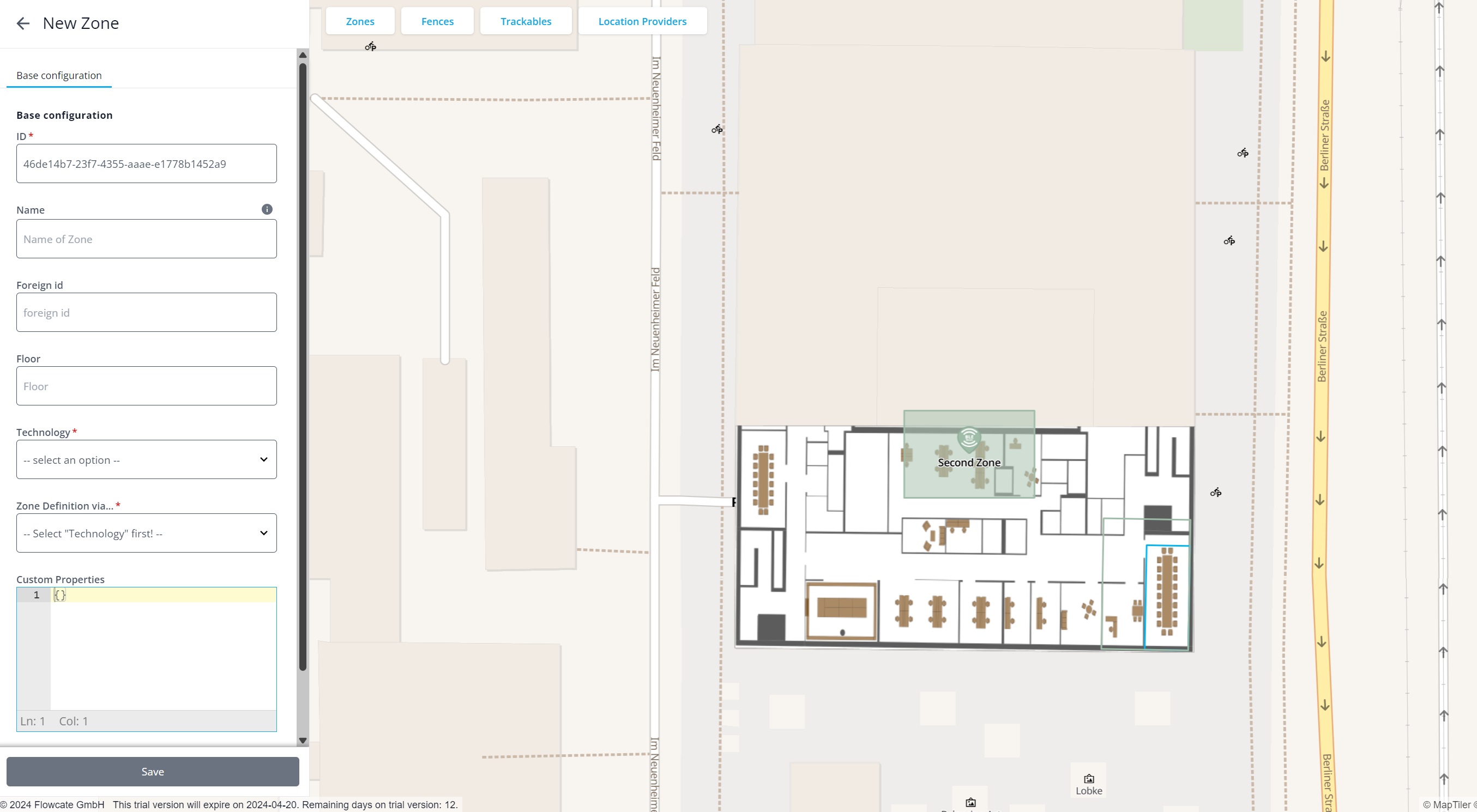
You may add your own "Name" for the zone, set a "Foreign id" if necessary and set a "Floor" number if the zone should be placed on a specific floor level.
Within the "Technology" selection, choose the technology for this zone.
If you choose UWB, BLE AoA, BLE Mesh or WiFi, you will implicitly create an RTLS zone. If you choose iBeacon or RFID, the zone will be a proximity zone!
The "Zone definition via ..." setting allows you to specify where on the map the zone should be placed.
If you have chosen a technology that has RTLS capabilities, you can define the zone in several ways:
- Providing the height and width for the zone, and one geographic coordinate on the map.
- Specifying local coordinates, and one geographic coordinate on the map.
- Drawing directly onto the map.
| RTLS Zone Definition Modes | Description |
|---|---|
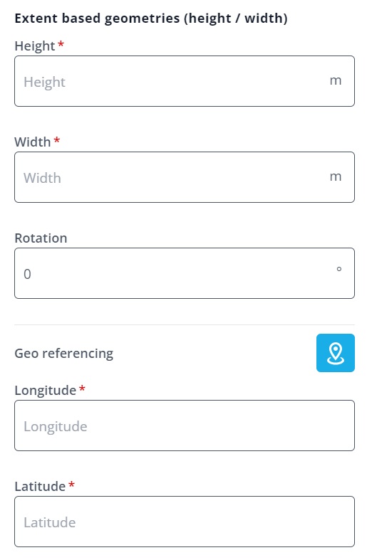 | Specify the desired height and width in meters, then click the blue "locate" button to the right of "geo-referencing". Finally, click on the map where you want to place the rectangle representing the zone. |
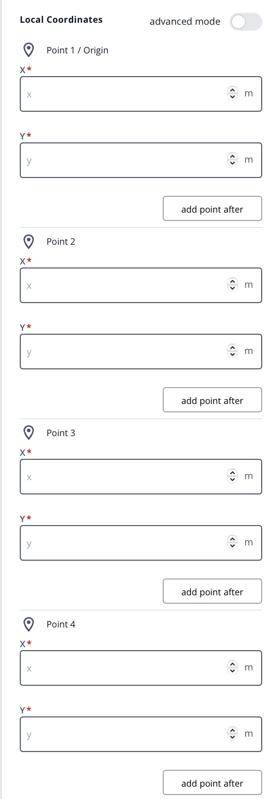 | Specify the local coordinates of the desired zone in meters for at least 4 points. The final step is identical to the "height and width" mode above: click on the blue "locate" button to the right of the "geo-referencing" section and then click on the desired position on the map. The "geo-referencing" section is below the point definition section and therefore not visible in the screenshot. The first point is treated as the origin. If you want to set an arbitrary position for the origin, activate the "advanced mode". Then you have the option to specify the origin in local coordinates. The corresponding fields to do this are located at the bottom of the creation widget. |
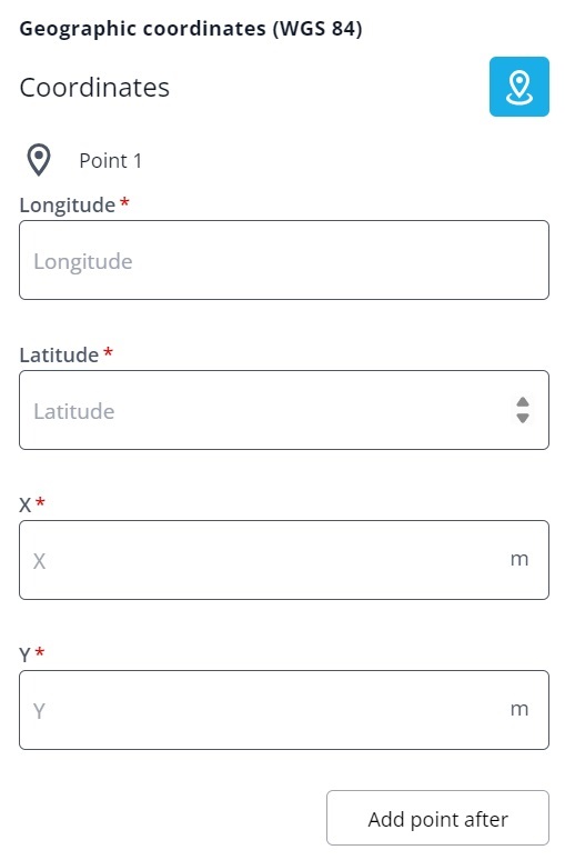 | Defining a zone via drawing on the map starts with a click on the blue "locate" button to the right of the "Coordinates" section. Then, click on the map for each corner point of the new zone. Do this at least 4 times to create 4 corner points. "Close" the zone by clicking on the first corner point. Then, add the local coordinates for each created corner point in the zone creation widget. You will see that the longitude and latitude coordinates for each corner point have already been added here. |
If you have chosen a proximity technology, only the "Drawing on map" option is available. After selecting this, a simple "Geographic Coordinates (WGS84)" widget will pop up. Here, you can either hit the blue "locate" button and then simply click on the map to get the global coordinates, or manually enter the longitude and latitude into the corresponding fields.
To create the zone, click the "Save" button at the bottom of the widget. If you want to cancel the creation, click the back arrow at the top of the widget, next to the title "New Zone".
Creation and Management of Anchors
The infrastructure of a real-time locating system consists of receivers placed on walls or ceilings, spanning an area within which tags can be located. These receivers are often called "anchors", "satellites" or "locators". They are represented in the DeepHub as "Anchor" entities. It is not mandatory to configure them within the DeepHub, however they help in providing a comprehensive overview of the system without having to switch to the software of the locating system vendor.
An anchor has "built-in" properties/attributes that are common for all real-time locating systems. Additionally, they may contain "custom properties" that store technology or vendor-specific information.
To create an anchor, choose "Create Entities" and then "Anchor". This will bring you to the "New Anchor" widget that shows a pre-generated Id for the new anchor to be created:
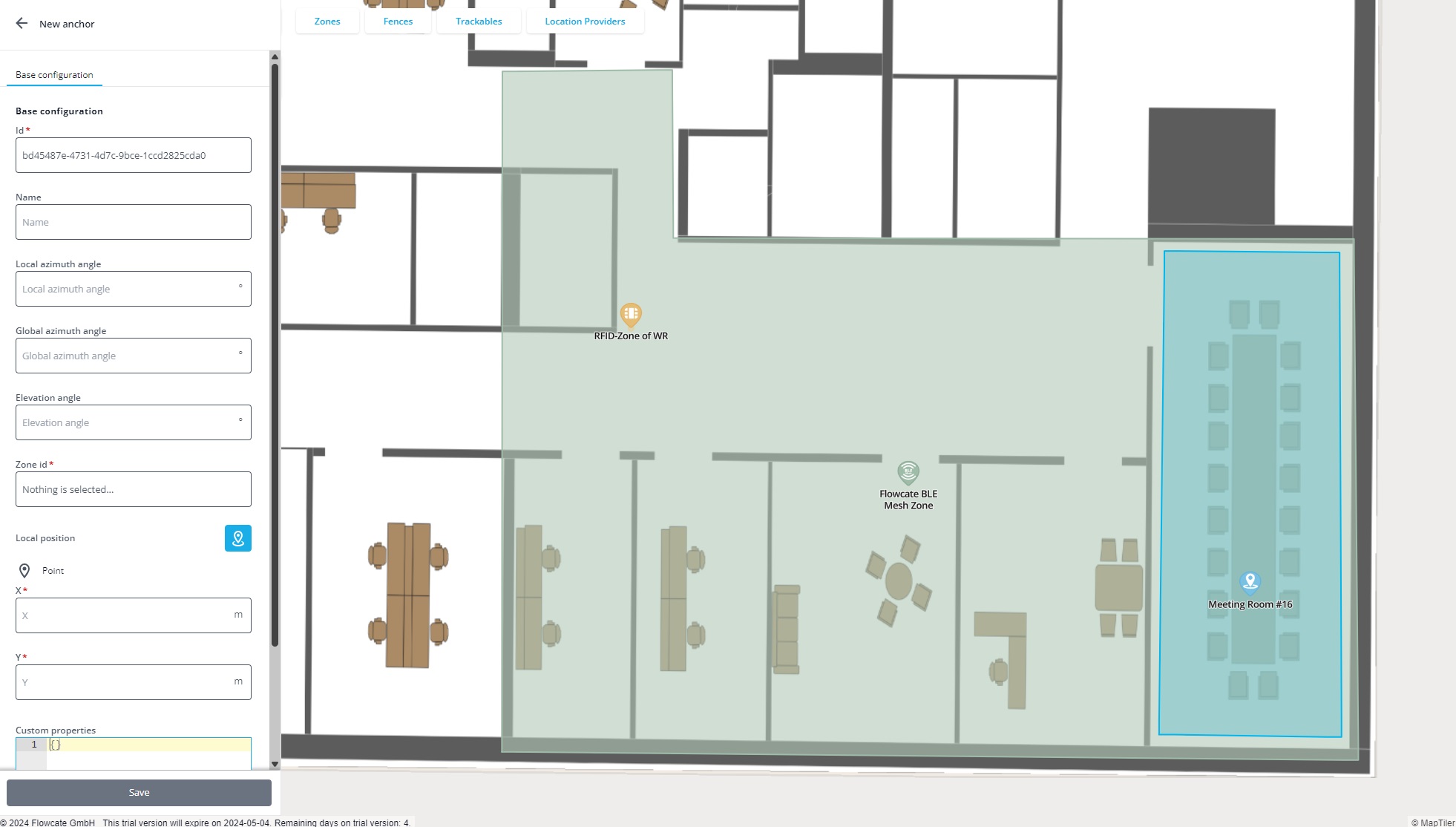
You may add your own "Name" for the anchor, set a "Local azimuth angle", a "Global azimuth angle" and an "Elevation angle".
Choose the zone to which the anchor will belong in the "Zone id" field.
The final step is setting the "Local position": it allows you to position the anchor on the zone to which it belongs, either by clicking on the map after clicking the "locate" button, or by manually entering the local coordinates.
Creation and Management of Location Providers
To create a location provider, choose "Create Entities" and then "Location Provider". This will bring you to the "New Location Provider" widget:
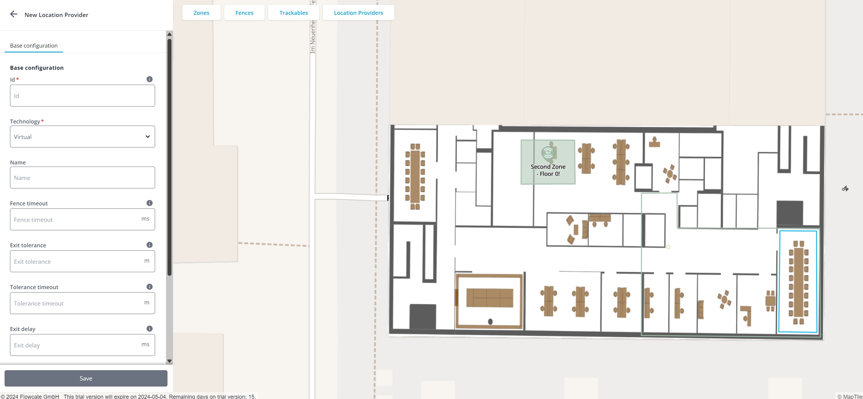
Unlike the other entity creation widgets, the Id field of the "New Location Provider" widget is not automatically populated with a generated Id. Instead, you may fill this in with a device specific identification number, such as a serial number, the MAC address (if it is a network-capable device), or a comparable unique identification number of the tag.
Choose the type of technology the tag supports in the "Technology" field. If a tag supports multiple technologies, select the primary technology type.
You may add your own "Name" for the location provider and set the fence-related properties: "Timeout", "Exit tolerance", "Tolerance timeout" and "Exit delay". Refer to the REST API documentation for location providers for a detailed description.
To create the location provider, click the "Save" button at the bottom of the widget. If you want to cancel the creation, click the back arrow at the top of the widget, next to the title "New Location Provider".
Business Logic and Application Level
The base entities of the DeepHub can be divided into two categories: the entities that represent the low-level abstraction of a locating system, and the entities that are used for business logic and application development. This chapter focuses on the latter, specifically: fences and trackables.
Applications interface with location updates via a trackable. A trackable refers to an actual object or asset being tracked, such as a forklift, truck, or worker. It may have one or more location providers attached to it. Therefore, a location update of a location provider subsequently leads to an update of the trackable's location as well.
A fence, or geofence, is an entity representing a geographical area/region of special concern. Trackables and location providers entering or leaving a fence trigger fence events. These events are delivered to clients and are therefore an integral ingredient for smart factory automation, where areas of a site are directly related to process steps. Therefore, entering or leaving an area represents a change of state within an application, such as an MES.
Creation and Management of Fences
To create a fence, choose "Create Entities" and then "Fence". This will bring you to the "New Fence" widget that shows a pre-generated Id for the new fence to be created:
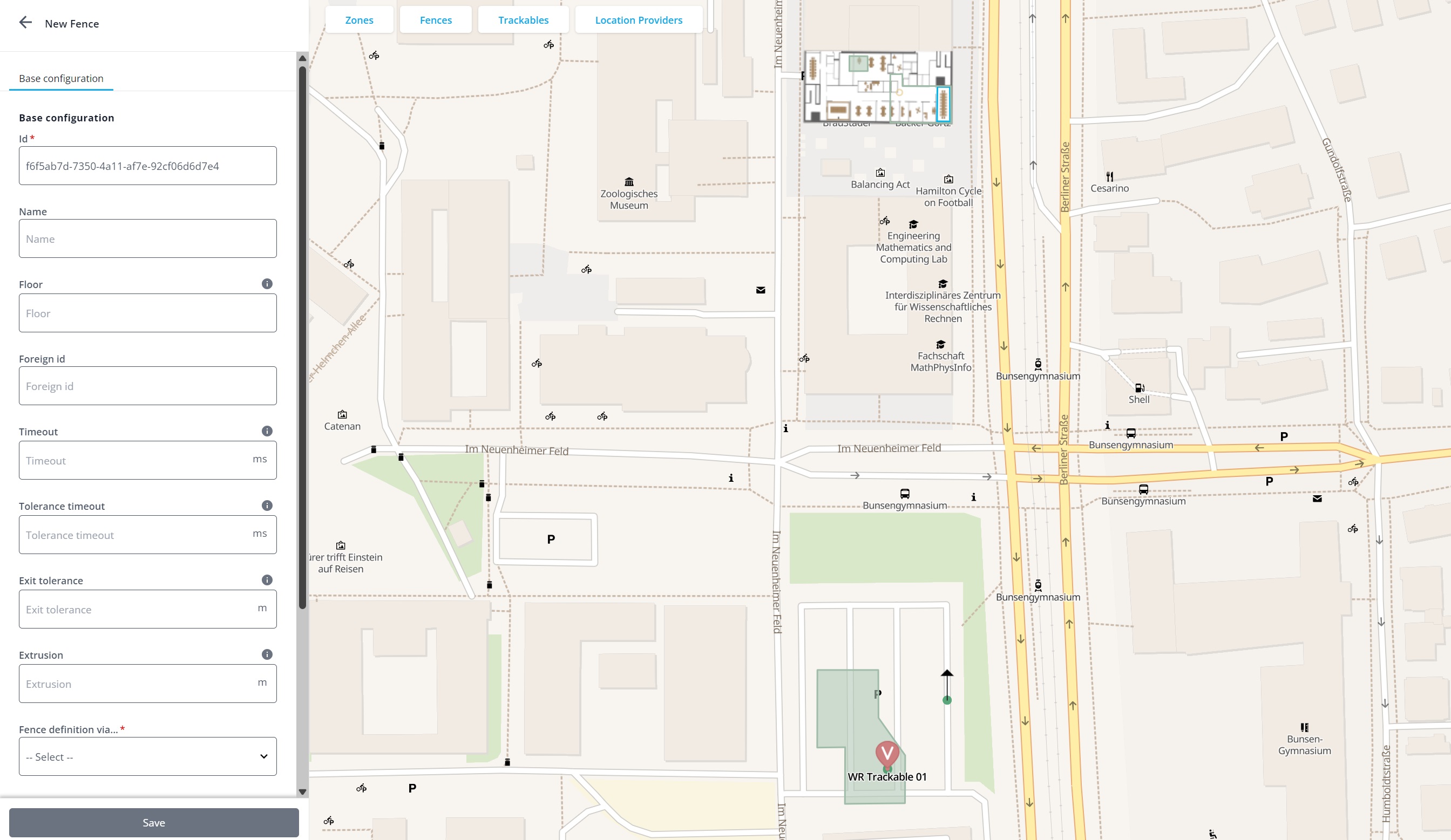
You may add your own "Name" for the fence, set a "Floor" number if the fence should be placed on a specific floor level, and set the fence-related properties: "Timeout", "Tolerance timeout", "Exit tolerance", and "Extrusion". Refer to the REST API documentation for fences for a detailed description.
The "Fence definition via ..." setting allows you to specify where on the map the fence should be placed:
| Fence Definition Modes via a Polygon | Description |
|---|---|
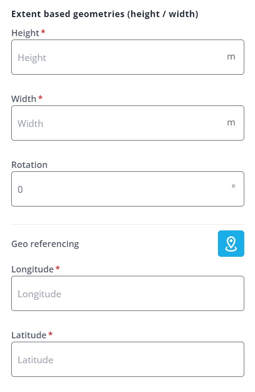 | Specify the desired height and width in meters, then click the blue "locate" button to the right of "geo-referencing". Finally, click on the map where you want to place the rectangle representing the fence. |
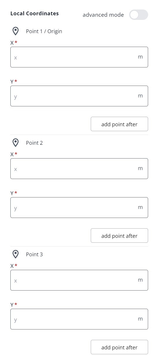 | Specify the local coordinates of the desired fence in meters for at least 3 points. The final step is identical to the "height and width" mode above: click on the blue "locate" button to the right of the "geo-referencing" section and then click on the desired position on the map. The "geo-referencing" section is below the point definition section and therefore not visible in the screenshot. The first point is treated as the origin. If you want to set an arbitrary position for the origin, activate the "advanced mode". Then you have the option to specify the origin in local coordinates. The corresponding fields to do this are located at the bottom of the creation widget. |
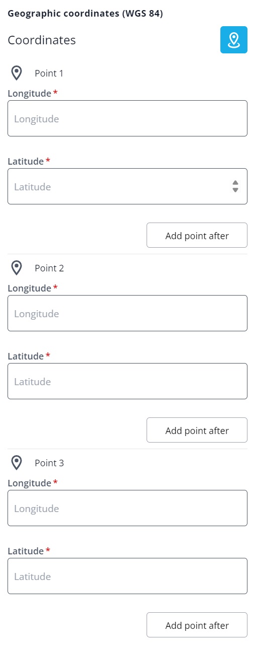 | Defining a fence via drawing on the map starts with a click on the blue "locate" button to the right of the "Coordinates" section. Then click on the map for each corner point of the new fence. Do this at least 3 times to create a polygon of 3 points. "Close" the fence by clicking on the first corner point. You will see that the longitude and latitude coordinates for each point have already been added. |
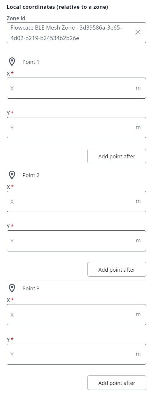 | In the "Local Coordinates (relative to a zone)" mode, first choose the zone from the "Zone Id" field, then specify the local coordinates of the desired fence in meters for at least 3 points. |
A fence may also be defined as a circle, where the center point and radius need to be specified:
| Fence Definition Modes via a Point | Description |
|---|---|
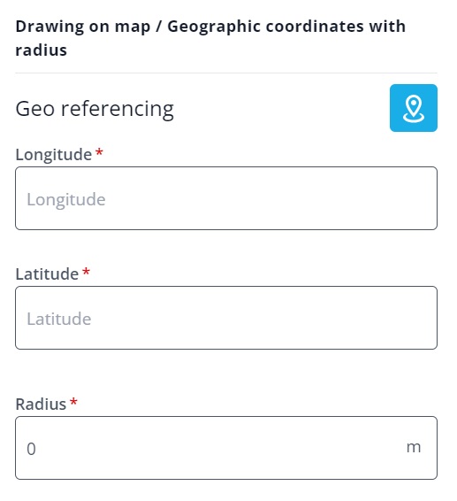 | Click the blue "locate" button to the right of "geo-referencing". Then, click on the map where you want to place the fence. Finally, add the radius for the fence in meters. |
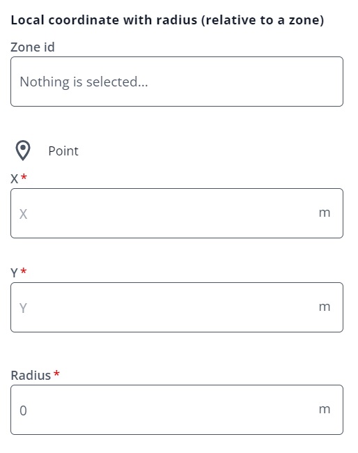 | Choose the zone from the "Zone Id" field, then specify the local coordinates of the center point of the fence. Finally, set the size of the radius in meters. |
Creation and Management of Trackables
To create a trackable, choose "Create Entities" and then "Trackable". This will bring you to the "New Trackable" widget that shows a pre-generated Id for the new trackable to be created:
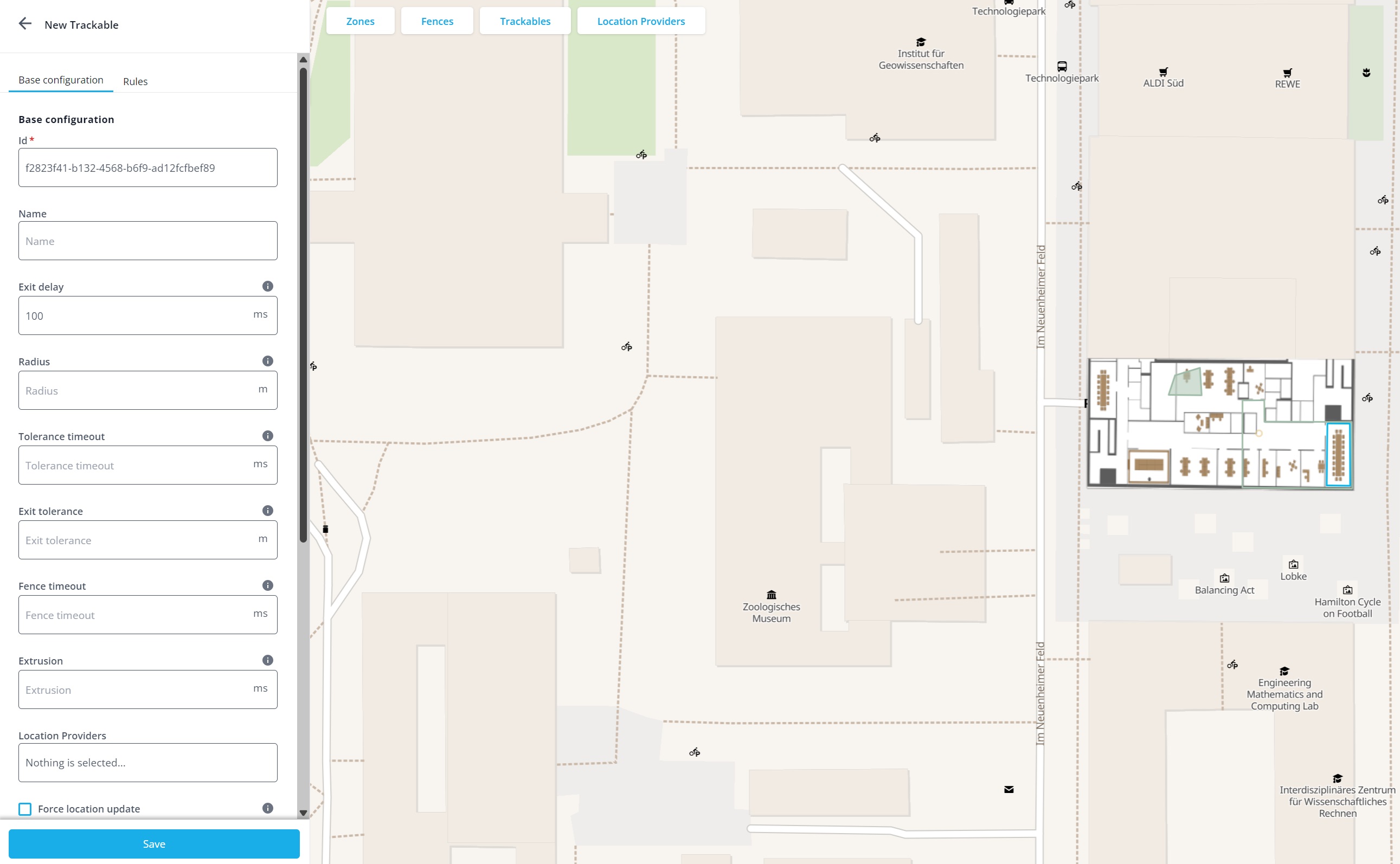
You may add your own "Name" for the trackable, specify a radius, tune the fence behaviour via the "Exit delay", "Tolerance timeout", "Exit tolerance", "Fence timeout" parameters and set an "Extrusion". Refer to the REST API documentation for trackables for a detailed description.
Attaching one or more location providers in the "Location Providers" field is not mandatory but an essential step: it is here where the magic between the business logic/application level and the locating system abstraction level happens.
Location providers are the low level entities that represent a tag and provide the actual locations. A trackable is the high level abstraction of an asset, and may be thought of as a digital twin. Attaching a location provider to a trackable is the way a trackable gets a location. If several location providers are attached, all of them may provide location updates. For example, a forklift may be equipped with an UWB tag for indoor tracking and a GPS receiver for outdoor tracking. Both would be represented as an individual location provider and both would be attached to one trackable representing the forklift.
Enabling the "Force location update" option causes the DeepHub to re-process the most significant location of the location providers assigned to this trackable when it is created. This is helpful and necessary for different use cases. For example, to trigger fence events for this newly created trackable if an associated location provider is currently within a fence.
The "deephub collision handling" option provides three different modes:
- Use the default based on the "calculate_collisions_default" parameter. The system-wide default is true; i.e. a trackable takes part in collision handling.
- Make this trackable NOT participate in collision handling.
- Take part in collision handling.
Finally, "Rules" can be applied for a trackable. Rules are optional and are valuable if more than one location provider is associated with a trackable. See the "Locating Rule Extension" chapter for details.
"API" of the DeepHub Admin UI
The DeepHub Admin UI offers several URL parameters to customize the map view.
Pan & Zoom to a specific location by specifying:
- lng: the longitude to which the map should pan.
- lat: the latitude to which the map should pan.
- zoom: the zoom level. Must be in the range [0,24], where 0 corresponds to a zoomed out view of the globe, and 24 corresponds to a detailed, zoomed in view. For more information, refer to MapTiler - our default mapping service provider: Tiles à la Google Maps.
map/live/show?lng=9.5367&lat=49.4055&zoom=9
OR:
- id: pan & zoom to the last known location of a trackable or location provider with the given id(s). If several ids are provided, they must be comma-separated.
- filterid: only render trackables and location providers with the given id(s). If several ids are provided, they must be comma-separated.
map/live/show?id=d49f0712-dcbd-4cbc-8b4f-c006b8555839